- output ripple
- Тематики
- См. также в других словарях:
- Choosing a capacitor? Ripple current capability matters as much as Farads
- Capacitor ripple current capability
- Calculating ripple voltage and current
- A note of caution
- The value of simulation
- Reader Interactions
- Comments
- Leave a Reply Cancel reply
- Ripple current at output capacitors
- How do you reduce voltage ripple?
output ripple
1 output ripple
пульсации на выходе
—
[Я.Н.Лугинский, М.С.Фези-Жилинская, Ю.С.Кабиров. Англо-русский словарь по электротехнике и электроэнергетике, Москва, 1999 г.]
Тематики
- электротехника, основные понятия
2 output ripple
3 output ripple
4 output ripple
5 output ripple
6 output ripple
7 output ripple
8 output ripple
9 output ripple
10 output ripple
11 output voltage ripple
12 пульсация выходного сигнала
См. также в других словарях:
Ripple (electrical) — The most common meaning of ripple in electrical science, is the small unwanted residual periodic variation of the direct current (dc) output of a power supply which has been derived from an alternating current (ac) source. This ripple is due to… … Wikipedia
Ripple — WikiV Amplitude variations in the output voltage of a power supply caused by insufficient filtering … Audio and video glossary
Buck converter — A buck converter is a step down DC to DC converter. Its design is similar to the step up boost converter, and like the boost converter it is a switched mode power supply that uses two switches (a transistor and a diode) and an inductor and a… … Wikipedia
Capacitance multiplier — A capacitance multiplier is a transistor configured such that it acts to multiply the value of the capacitor connected to its base by an amount equal to the transistor s current gain (β). This circuit is usually found in DC power supplies where… … Wikipedia
Flyback converter — The Flyback converter is a DC to DC converter with a galvanic isolation between the input and the output(s). More precisely, the flyback converter is a buck boost converter with the inductor split to form a transformer, so that the voltage ratios … Wikipedia
Ćuk converter — Cuk redirects here. For the Idel Ural festival, see Çük. The Ćuk converter (pronounced Chook, sometimes incorrectly spelled Cuk, Čuk or Cúk) is a type of DC DC converter that has an output voltage magnitude that is either greater than or less… … Wikipedia
Vicor Corporation — Infobox Company company name = Vicor Corporation company company type = Public (nyse|VICR) foundation = 1981 location = Andover, MA key people = Patrizio Vinciarelli (Chairman of the Board, President and Chief Executive Officer), Barry Kelleher… … Wikipedia
Voltage regulator — A popular three pin 12 V DC voltage regulator IC. A voltage regulator is an electrical regulator designed to automatically maintain a constant voltage level. A voltage regulator may be a simple feed forward design or may include negative feedback … Wikipedia
Continuously variable transmission — Transmission types Manual Sequential manual Non synchronous Preselector Automatic Manumatic Semi automatic Electrohydraulic Dual … Wikipedia
пульсации на выходе — — [Я.Н.Лугинский, М.С.Фези Жилинская, Ю.С.Кабиров. Англо русский словарь по электротехнике и электроэнергетике, Москва, 1999 г.] Тематики электротехника, основные понятия EN output ripple … Справочник технического переводчика
Voltage multiplier — Villard cascade voltage multiplier. A voltage multiplier is an electrical circuit that converts AC electrical power from a lower voltage to a higher DC voltage, typically by means of a network of capacitors and diodes. Voltage multipliers can be… … Wikipedia
Источник
Choosing a capacitor? Ripple current capability matters as much as Farads
by Derick Stephens, KEMET Corporation
Selecting capacitors for decoupling and filtering in power circuits may seem like a basic chore for electronics designers. Getting it right, however, can critically influence reliability and longevity, but is complicated by the fact that parameters tend to change with factors such as the temperature and operating frequency. Proper attention should be paid to capacitor selection, taking advantage of the technical resources now more widely available online to simplify and accelerate the process.
Capacitor ripple current capability
In power-conversion circuits, such as AC/DC power supplies, DC/DC converters, and even DC links, capacitive filters are needed to counter fluctuations that cause instability. Success is usually manifested as a lack of noise present in the DC power output and free of disturbances transferred into nearby circuitry.
The fluctuations in question are superimposed on the ideal, stable waveforms. Interference can arise from a variety of sources. One common source of noise is the rectification of AC; the resultant DC output from a rectifier usually has some amount of the source AC content superimposed on it. Switching regulators of all types create a certain amount of ripple when performing its primary function. Good designs usually try to mitigate this ripple as much as possible, but it can’t be completely eliminated. As a general principle, the capacitors are placed in the circuit to absorb and discharge the energy associated with these fluctuations on a continuous basis, and so minimize the peaks and troughs.
As a result of this action, the capacitor continuously passes a varying current. This current is called ripple. Although ripple current is the inevitable result of the capacitor performing its required task, it causes undesirable I2R heating as it passes through the Equivalent Series Resistance (ESR) that is associated with any capacitor. If the I2R effects exceed the capacitor’s ability to dissipate heat, its temperature can rise and hence adversely affect reliability. At the least, the component lifetime may be affected according to the Arrhenius Law, which states that lifetime is reduced by half for every 10°C increase in operating temperature. More extreme heating, exceeding the specified maximum temperature, can destroy the capacitor by causing drying or boiling of liquid electrolyte, cracking of ceramic capacitors, or ignition. A heatsink could be used to limit the temperature rise, if the application space and weight constraints allow. On the other hand, calculating the ripple current and understanding the properties of suitable capacitors can help to achieve the most space-efficient and cost-effective solution.
The capacitor datasheet indicates a ripple current rating that broadly describes the maximum ripple the device can withstand. This can be used as a guide, with the understanding that it is evaluated under controlled conditions. These are defined in standards such as EIA-809 or EIA/IS-535-BAAE, although there is some ambiguity in these documents. To help engineers understand the issues surrounding ripple current, KEMET has published an article, Ripple Current Confusion, in its online technical library (ec.kemet.com), which describes these standards and their applicability in detail. Discrepancies in the measurement of ripple current capability prevent easy direct comparisons between the ripple current capabilities of different manufacturers’ capacitors. Datasheet figures are useful, however, for comparing products from the same manufacturer.
Calculating ripple voltage and current
To choose the right capacitor for the input filter of a switching regulator, for example, the capacitance needed to achieve a desired voltage ripple can be calculated, if the operating conditions of the regulator are known. When the capacitance is calculated, a candidate component can be identified, and the ripple current determined from the known ESR. This ripple current must be within the capacitor’s ripple current handling capability, if the device is to be suitable for use. This is where selection can become difficult, because both ESR and capacitance are known to vary with temperature, operating frequency, and the applied DC bias.
The capacitance can be calculated using the equation (from TI Application Report SLTA055)

Where CMIN = minimum capacitance required
IOUT = output current
dc = duty cycle (usually calculated as dc=Vout/(Vin*Eff))
fSW = switching frequency
VP(max) = peak-to-peak ripple voltage
Assuming, for example, a regulator with 12v input; 5v output; 2amp output; 85% efficiency; 400kHz switching, and an allowable input ripple voltage of 65mV:

Note that the chosen device must provide this value of capacitance at the regulator operating frequency of 400kHz.
The rms value of the peak-to-peak ripple voltage can be calculated from the equation:
The ripple current in the capacitor can then be calculated by applying Ohm’s law, if the capacitor’s ESR is known.
A note of caution
At this point, the variability of capacitor properties, according to operating conditions, must be considered. Most engineers understand the temperature stability issues of class II/III dielectrics. Fewer understand the magnitude of capacitance loss due to the operating frequency and the applied voltage.
Recall that 19.22µF, as calculated earlier, is the capacitance required at the regulator’s operating frequency of 400kHz. The ESR must also be known at this frequency, to calculate the ripple current.
If a capacitor with nominal capacitance of 22µF and voltage rating of 16V is chosen, as the nearest standard value above 19.22µF, the actual capacitance of this device is 5.951µF at 400kHz, as shown in figure 1, and the ESR is 3.328mΩ. The resulting ripple voltage and current can be calculated as 210mVp-p/74.23mVrms, and 22.3A respectively. These are significantly greater than the target ripple voltage and maximum allowable ripple current for the capacitor.
 Figure 1. capacitance loss with frequency.
The value of simulation
Every manufacturer of Class ii components will advocate simulating the component behavior allowing for application voltage, temperature and frequency. KEMET’s K-SIM online electrical parameter simulator lets engineers assess capacitor performance under a variety of operating conditions. it is available in the KEMET Engineering Center, alongside the ripple-voltage calculator mentioned earlier and other tools and support information including technical notes and application guides.
Using K-SIM, engineers can quickly analyze one or multiple capacitors that may be suitable for the application they are working on. Among the various features, K-SIM can display impedance and ESR, or capacitance and voltage versus operating frequency, and also predict temperature rise depending on ripple current and frequency. An on-screen cursor helps ensure accurate measurement. K-Sim also allows capacitor S parameters to be evaluated, and SPICE models and STEP files obtained for components of interest.
With the aid of this tool, a 47µF X5R capacitor was identified, with the same case size and voltage rating as the 22µF/16V device selected earlier. The capacitance value is 19.9µF at 400kHz under the applied DC bias, and thus restricts the peak-to-peak ripple voltage to 63mV. Hence Vrms = 22.27mV. This capacitor’s ESR is 3.246mΩ at 400kHz, suggesting the ripple current is 6.86A, which is below the maximum for the device.
Conclusion
The issue of ripple current can be challenging to analyze and to predict accurately under expected circuit-operating conditions. When left unchecked the heating caused by ripple currents can adversely affect the life of the capacitor. Nevertheless, proper assessment of the ripple voltage and current is vital, to ensure a power circuit like a switching regulator will deliver the required performance over its intended lifetime. Online tools and information provide valuable help to calculate the capacitance needed and accelerate component selection.
Reader Interactions
Comments
ripple current of 1 component with 47uf capacitance is 110mA, however for the other component with same capacitance value has a 115mA, also they have 25V of rated voltage and with 20% tolerance. Does it mean that these 2 components is the equivalent or similar?. they only differ in ripple current.
Leave a Reply Cancel reply
This site uses Akismet to reduce spam. Learn how your comment data is processed.
Источник
Ripple current at output capacitors
I was reading about the selection of output capacitors at the output of buck converters and found this Link
The accepted answer states that before I select an output capacitor, we must fix the desired ripple current and then choose the inductor based on the ripple current.
- How to choose and fix the ripple current? Should we just assume the ripple current to be 20 to 40% of Iout max current as mentioned in the TI App Note and proceed with those calculation steps.
I am not sure I get this. I always thought that the selection of output capacitor was based on ripple voltage.
For example, If I have an IC Whose Vcc ranges from 0.8V to 1.2V and typical Vcc is 1V. My Buck will produce 1V with a ripple that must not exceed the Min and Max Vcc of the IC. So, my ripple should be less than 200mV. So, here, obviously our ripple voltage is very important. If the ripple voltage is very high, then our 1V IC may get damaged. But we also calculate ripple current.
- How is the ripple current more important that the ripple voltage. What happens if we have high ripple current and low ripple current?
So, I think we would select a capacitor based on our calculated ripple voltage (To be less than 200mV).
- So, is our estimate of Inductor ripple current same as the output capacitor ripple current ?
I tried other app notes also. But I couldn’t find a formula that mentions the calculation of output capacitor ripple current. And can someone tell me how output ripple voltage and output capacitor ripple current are related and which is calculated first and based on what parameter.
Источник
How do you reduce voltage ripple?
Introduction
- Ripple Voltage
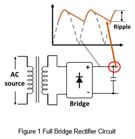
Ripple voltage means the amount of AC voltage that appears on a DC voltage. The main reason for the ripple voltage is that the converter converts the AC voltage into a DC voltage, but the AC voltage cannot completely eliminate. For example, Figure 1 is a schematic diagram of a full bridge rectifier with a capacitor connected to the output side. The dotted line is the voltage waveform before full bridge rectifier, the solid line is the voltage waveform after capacitor filtering, and the ripple voltage refers to the peak-to-peak value of the solid line.
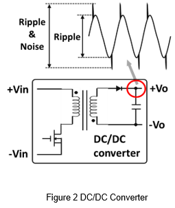
The ripple voltage shown in Figure 1 is low frequency ripple voltage. In higher frequency applications, such as AC to DC or DC to DC converters, the frequency of the ripple voltage maybe be higher. Figure 2 is a schematic diagram of a DC/DC converter. The voltage noise is generated during the MOSFET switching and coupled to the output side through the transformer. And finally the ripple measured at the output capacitor is a ripple voltage that contains noise components.
- Measurement Methods
The general method of measuring voltage is to use a voltage probe to measure the output or load side as shown in Figure 3. And display the volume of the output voltage through an oscilloscope. However, if used the same methods to measure the ripple voltage, the waveform is susceptible to interference.
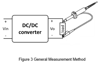
Figure 4 shows the ripple voltage measured using a general measurement method. It can be seen that the noise part is significantly higher. This is mainly due to the long ground wire of the probe. The measurement path for the probe is equivalent to the increase of parasitic inductance, which causes noise in the output voltage waveform. This is not caused by the converter, and it is easy for misjudgment. So, the correct measurement method is very important.
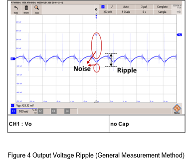
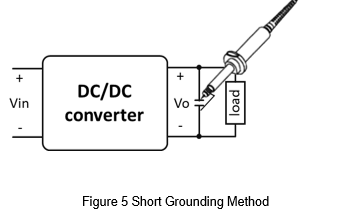
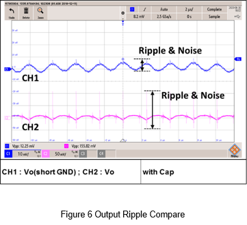
Figure 5 shows the correct ripple measurement method. It can be seen from the figure that the output of the converter is connected with a filter capacitor. The purpose is to suppress noise, so the capacitor value is usually not too large, mostly at 0.1uF to 1uF. And the probe should use a short grounding method for measurement. The measure point should change from the load to the output capacitor. The purpose is to avoid measuring noise. Figure 6 shows the difference between the ripples of short ground and no short ground. The ripple voltage of the converter can be measured correctly if used the right methods.
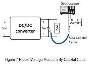
Most ripple voltage measurements are when the oscilloscope is close to the converter. If the distance is relatively long, it may not be suitable to use a voltage probe for measurement. The more suitable method is to use a 50Ω BNC connector and a coaxial cable for long-distance measurement, as shown in Figure 7. It should be noted that the shorter the cable length from the output end of the coaxial cable to the capacitor and the oscilloscope, the less likely it is to receive interference.
This article is using voltage probe and short ground method and used 20MHz bandwidth to measure the ripple voltage.
External Circuit For Reduce Ripple & Noise
The following will list four external circuit and explain the theory for the schematic.
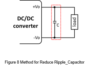
As shown in Figure 8, Connecting a capacitor to the output of the converter is a simple way to reduce the output voltage ripple.
Take full bridge converter as an example.
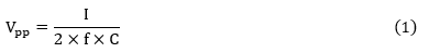
Vpp is the peak-to-peak value of the ripple voltage.
I is the output current.
f is the operating frequency.
C is the capacitance.
As shown in formula (1), the ripple voltage is inversely proportional to the capacitance. That is, the larger the capacitance, the smaller the ripple voltage. Which shows that the external capacitor helps to suppress the ripple voltage.
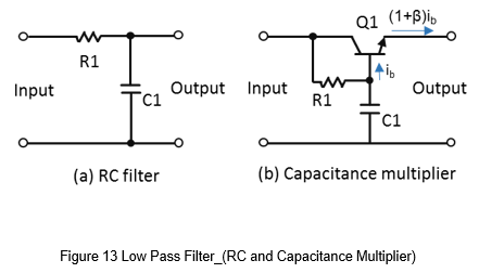
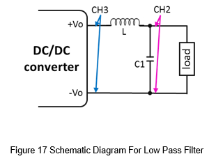
A low pass filter maybe a good chose to reduce the ripple voltage more than a capacitor, as shown in Figure 9.
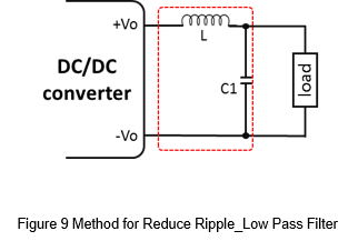
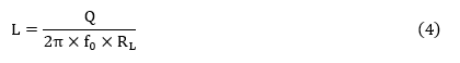
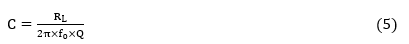
It can used frequency response to calculate the parameters of L and C.
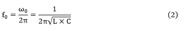
f0 is Cutoff frequency.
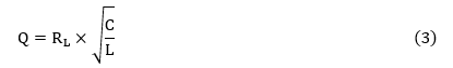
Q is Quality factor.
RL is Output load.
Take formula (3) into formula (2), and it can calculate the L and C respectively, as shown in formula (4) and (5).
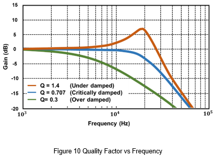
The quality factor is related to the load impedance and the LC filter, which can be divided into three curves of over damping, critical damping and under damping, as shown in Figure 10. Ideally, the use of critical damping as the parameters of the LC filter is most suitable.
- Common Mode Choke Filter
Due to there has some switching components inside the converter, and it will generate switching noise. These noises may also be transmitted to the output side. And the common mode choke filter can limit this kind of noise, as shown in Figure 11.
Common mode choke filter is commonly used as an EMI filter. However, there is still leakage inductance inside the common mode filter. The leakage inductance act as a differential mode inductor, and it similar as the LC rate filter. So, the common mode filter inductor can still have some effect on ripple voltage suppression.
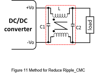
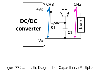
Figure 12 shows the capacitance multiplier circuit, and it can reduce the output ripple by transistor and R, C. For the output side, it has the effect of amplifying C1, similar as add a large capacitance at the output side. It is suitable for need to reduce ripple voltage and have size limit application.
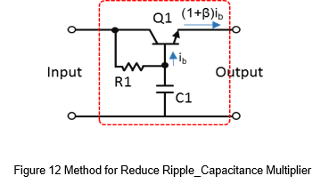
As shown in Figure 13 (a), it is a RC low-pass filter in the circuit. If want to suppress the voltage ripple, the capacitance of C1 must be very large. If a transistor is added to this, as shown in Figure 13(b), the current supplied by C1 to the output is about β times down. In other words, the capacitance of C1 is amplified by about β times to the output.
The capacitance multiplier circuit also has disadvantages, because the voltage of the transistor Vce will change with the output current, which will cause a certain voltage drop at the output side, the range maybe from 0.65V to 3V. Therefore, this is suitable for small current application and the voltage accuracy is not high, such as an OP amplifier or a DAC power supply.
Application
In the following, a specific DC-to-DC converter will be used to measure the difference in ripple voltage before and after through different ripple voltage reduce circuits.
The converter is a wide input voltage range from 9 to 36V input, 5V output regulated converter, the output power is 30W, the output current is 6A, the specifications are shown in Table 1.
| DC to DC Converter | PF30WR4-2405 |
| Input voltage | 24 Vdc |
| Output | 5 Vdc / 6A |
| Operating frequency | 400kHz |
| Ripple & noise | 75mVp-p (max) |
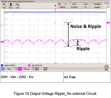
Figure 14 shows the voltage ripple waveform of output by using a short ground method. Due to there are no additional noise suppression circuit. It can be seen that the peak-to-peak value of the output voltage ripple and noise is about 445.9mV when there is no external capacitor.
In order to suppress the output voltage ripple and noise, the most common and simple way is add the capacitor.
Figure 15 shows the output voltage ripple measured by an external 22uF MLCC. From the figure, the ripple voltage reduced from 445.9mV to about 30mV.
In addition, Figure 16 show the waveform for double the output capacitor. The output voltage ripple becomes lower and the peak-to-peak value is 19.5mV. Therefore, an external capacitor at the output of the converter can effectively suppress the output voltage ripple.
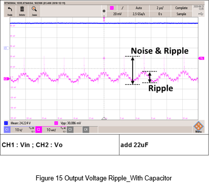
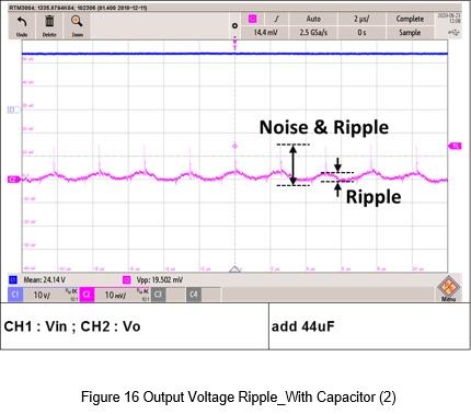
Fig. 17 is a schematic diagram of a low-pass filter. From the converter specification table, the converter operating frequency is 400kHz. First set the cut-off frequency to 40kHz and the quality factor to 0.707. Through equations 4 and 5, it can get the inductance is 4.69uH and the capacitance is 3.376uF. Finally choose 4.7uH inductance and two 2.2uF MLCC as the output low-pass filter.
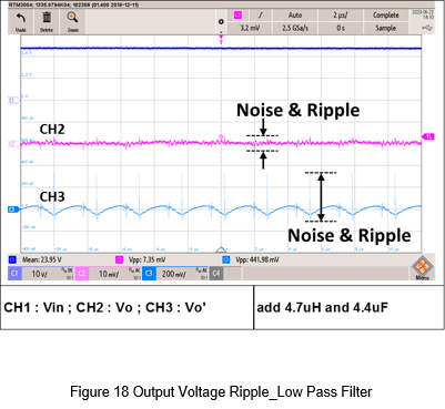
Figure 18 is a waveform of the output voltage ripple. There is a comparison before and after filter. The low-pass filter, the ripple and noise are effectively suppressed.
- Common Mode Choke Filter
Figure 19 is a schematic diagram of common mode choke as an output filter. In this experiment, a Mn-Zn ferrite core of A151, T16x12x8C used as an iron core. The number of windings is 10. The main inductance is 0.35mH, and the leakage inductance is 3.18uH. C1 and C2 is 0.22uF MLCC.
Figure 20 is a schematic diagram of a common mode filter. It can be seen that the leakage inductance is used as a differential mode inductance, which is the same as two low-pass filters, so the output voltage ripple suppression effect should better than single low-pass filter.
Figure 21 is the measure waveform. It is true that the ripple voltage is lower than single low pass filter, but the disadvantage is that it takes more layout space.
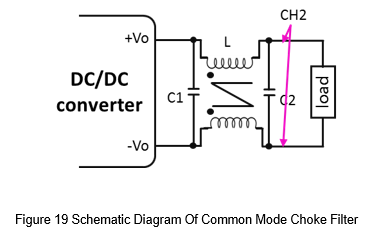
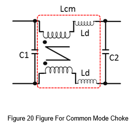
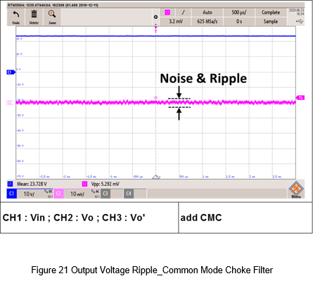
Figure 22 shows the schematic diagram of this experiment, the parameters are as follows.
Q1 is 2SCR552PT100, it is a transistor of ROHM.
Since the capacitance multiplier is suitable for low power or signal level. Because it will cause voltage drop, it is not suitable for high current applications. So, the output current of this experiment is limited to 0.2A.
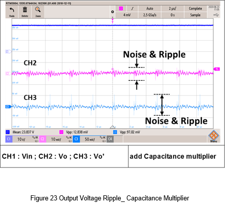
Figure 23 is the test waveform. It can see the difference between before and after filter. The ripple before suppression is about 97mV and the ripple after suppression is 12.8mV, which can reduce the voltage ripple. The disadvantage is that it can only be used in signal level, instant of higher output power.
Conclusion
This article has introduction about the formation of ripple and noise, and the measurement method. Also provides four kinds of ripple and noise reduction methods, and do the experiment for each kind of filter.
Table 2 shows the comparison table for the four methods, the lower the score the better.
From the overall score, only the addition of capacitors is the most suitable ripple suppression method, which not only has the smallest volume but also has a certain effect.
The second and third are low pass filter and common mode filter. Because it has external inductors and common mode choke, the layout space is larger than capacitor, but the effect is better. Therefore, many low ripple applications are used these two methods.
The fourth is the capacitance multiplier circuit, which has a good effect on the suppression of ripple voltage, but it can only be used for low current or signal level, which limits the application.
| C | LC filter | CMC filter | C multiplier | |
| Part count | 1 | 2 | 3 | 3 |
| Layout space | 1 | 2 | 3 | 3 |
| Ripple & Noise suppression | 2 | 1 | 1 | 1 |
| Output current | 1 | 1 | 1 | 3 |
1→Good, 2→Middle, 3→Poor
CTC is a professional service provider for high-end power supply modules (AC to DC Converter and DC to DC Converter) for critical applications worldwide since 30 years. Our core competence is to design and deliver products with leading technologies, competitive pricing, extremely flexible lead-time, global technical service and high-quality manufacturing (Made In Taiwan).
CTC is the only corporation certificated with ISO-9001, IATF-16949, ISO22613(IRIS), and ESD/ANSI-2020. We can 100% ensure not only the product, but also our workflow and service to match quality management system for every high-end application from the very beginning. From design to manufacturing and technical support, every single detail is operated under highest standard.
Источник